
A twin-motor RC airplane needs a clear plan for three things: power to each motor, a throttle signal to each ESC, and power for the receiver and servos. The diagrams below show two conventional arrangements using separate brushless ESCs: one shared flight battery, or one battery for each motor.
Part of the RC Airplane Electric Power System Center.
Before changing wiring, disconnect every battery and remove both propellers. These are functional diagrams, not connector pinouts. Check the exact ESC and receiver manuals, connector polarity, voltage limits, and current ratings.
Both examples use ordinary PWM throttle leads and one ESC’s built-in BEC to power the radio. Opto-isolated ESCs, no-BEC controllers, integrated dual ESCs, and proprietary control systems can require different connections.
What connects to what?
For the two separate ESCs shown here, each controller connects to its own brushless motor. A receiver throttle Y-harness sends the same command to both ESCs. That small receiver harness is separate from the high-current battery wiring; it does not carry motor current.
Each brushless motor needs its own motor-control output. An integrated dual ESC provides two outputs in one unit. Do not connect two motors to the same three phase wires on a normal single-motor brushless ESC.
| Decision | One shared battery | Two separate batteries |
|---|---|---|
| Motor supply | A power splitter feeds both ESCs. | Each pack feeds its own ESC. |
| Battery workload | The pack and common connector carry the combined load. | Each pack carries its own side’s load. |
| Layout | One pack to mount, access, and charge. | Two packs to secure, charge, and check. |
| Receiver supply shown | ESC A’s BEC. | ESC A’s BEC, supplied by battery A. |
| Backup radio power? | No. | No. A second motor battery does not create it. |
Diagram 1: one battery, two ESCs, two motors

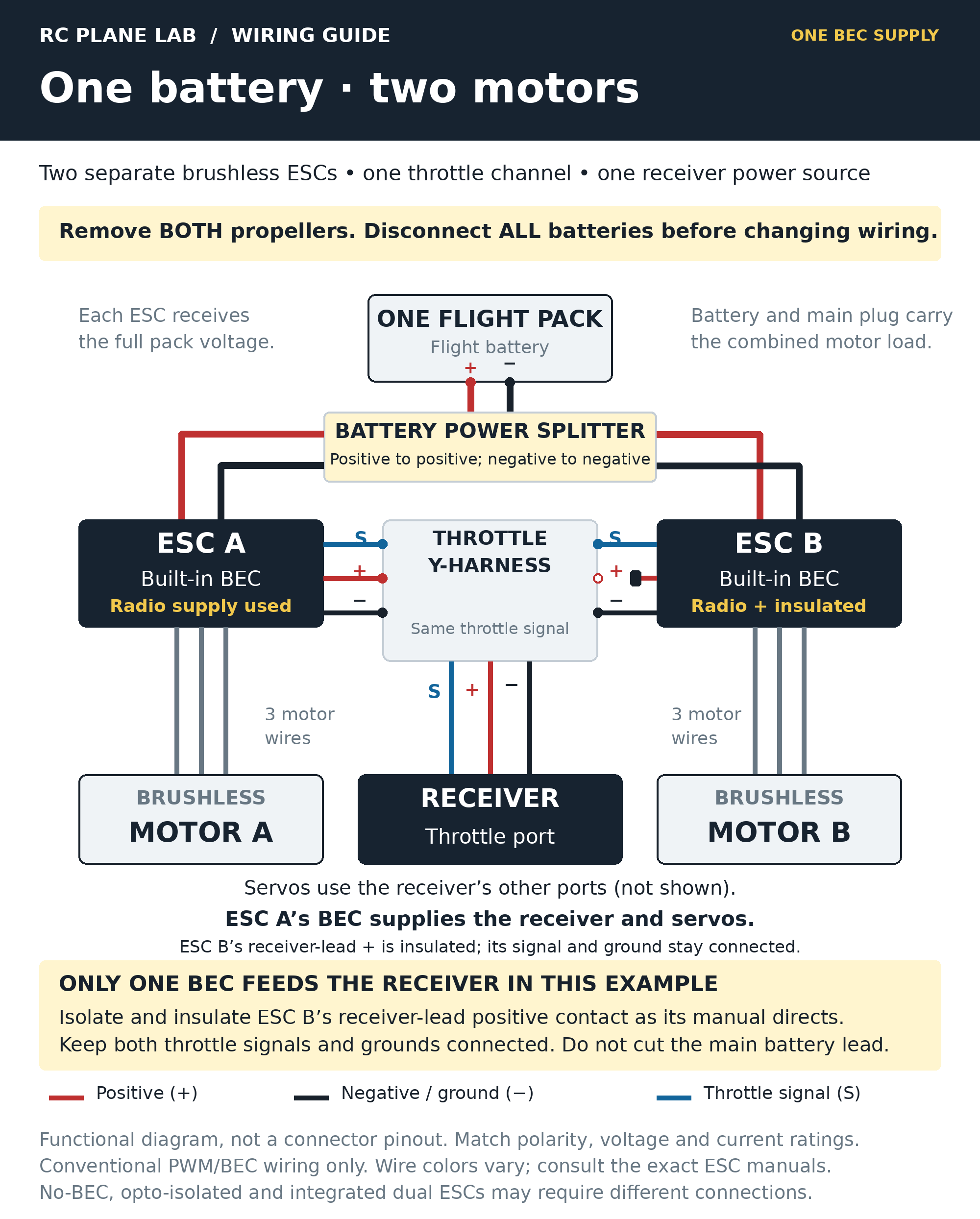
Connect battery positive to both ESC positives and battery negative to both ESC negatives through a properly rated power splitter. Each ESC’s three motor wires go only to its own motor. The receiver connections are explained in BEC and receiver power below.
Illustrative current example: if the two motor branches draw 22 A and 24 A simultaneously, the shared supply carries about 46 A, plus any additional load not included in those branch measurements. Each ESC is sized for its own motor; the shared battery connector and wiring must handle the total. These example numbers are not a connector or ESC recommendation.
Diagram 2: one battery for each motor

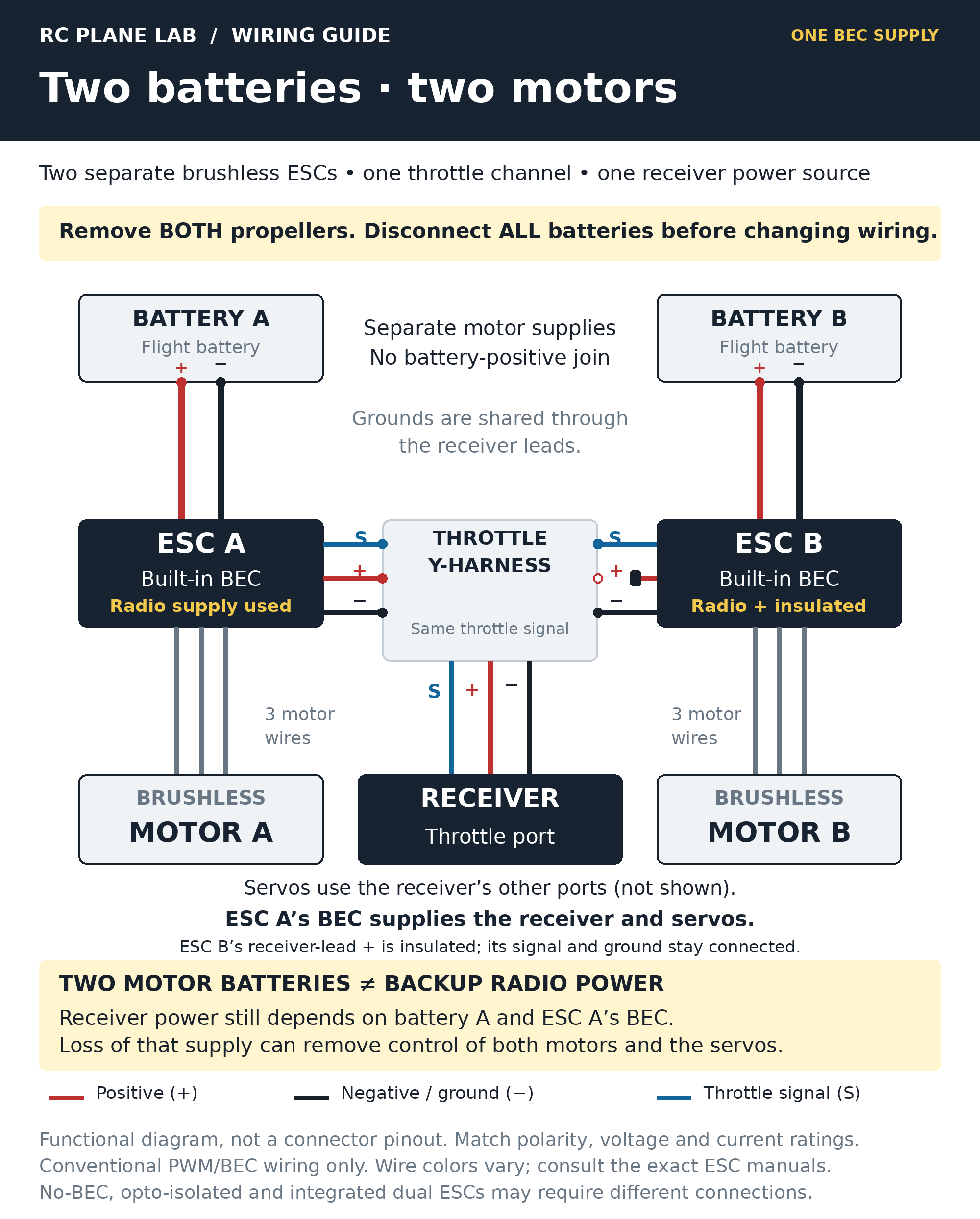
Check both packs before every flight and label them so you can track each side. Battery placement must also satisfy the airplane’s center-of-gravity and lateral-balance requirements.
Two motor batteries do not mean redundant receiver power. In this drawing, the receiver and servos depend on battery A and ESC A’s BEC. Losing that supply can remove control of the whole airplane even while battery B is still charged. A backup radio system requires a purpose-designed, compatible power arrangement.
BEC and receiver power: choose one supply deliberately
The diagrams designate ESC A as the radio power source. Its receiver lead keeps signal, positive, and ground connected. ESC B keeps signal and ground connected, while its receiver-lead positive contact is isolated and insulated according to the controller’s instructions. The Model Aviation multimotor article describes this conventional shared-throttle arrangement.
Identify the contact by function, not just wire color. The red line in the diagrams means positive. Actual lead colors and pin order vary. The contact being isolated is on the small receiver lead, not either main battery wire. A correctly made, clearly labeled removable adapter can preserve the original ESC lead.
Do not assume two BEC outputs can be joined because their nominal voltages match. Use parallel supplies only when the manufacturers explicitly support that arrangement. For example, the Castle CC BEC Pro manual prohibits another BEC or backup receiver pack connected in parallel on its receiver/servo side.
Size the chosen BEC for the receiver, all servos, retracts, and other devices it actually supplies. Check output voltage, continuous and peak current, input-voltage derating, cooling, and the connectors in the supply path. A high motor-current rating says nothing by itself about BEC capacity.
External BEC or no built-in BEC? Follow that equipment’s wiring instructions instead of copying the positive-lead change automatically. The Castle Phoenix Edge HV manual, for instance, specifies external receiver power and says its red throttle-lead wire does not need to be disconnected. See ESCs and BECs explained for the broader selection process.
Check current, connectors, and wire routing
- Match each side. Check motor, propeller, battery cell count, and ESC ratings together. Compare equivalent current measurements on both sides; investigate a large unexplained difference before flying.
- Plan cooling and access. Give both ESCs the airflow their manufacturers require. Secure connectors and protect wiring from sharp edges, moving linkages, and wing-joint strain.
- Check extensions before building them. Long battery-to-ESC leads can increase inductance and voltage ripple. Castle’s capacitor-pack guidance explains the issue. Ask the ESC manufacturer about allowed lengths, wire gauge, and additional capacitance; do not apply one brand’s limit to every controller.
Use the motor, ESC, battery, and propeller matching guide and electrical connectors and wiring guide when selecting the hardware.
Before flying: verify both sides
- Start with both propellers removed and all batteries disconnected. Inspect polarity, connector engagement, insulation, the selected receiver supply, and the isolated positive contact.
- Configure the radio and ESCs using their manuals. Confirm throttle direction, endpoints, brake, battery type/cell count, cutoff behavior, and motor direction. Calibrate each ESC if its manufacturer requires it; the Hobbywing Skywalker V2 manual is one example with a specific calibration procedure.
- Check arming and low-speed response with the props off. Both motors should respond consistently. A common throttle command does not guarantee identical RPM. Investigate hesitation, stuttering, or a large startup mismatch.
- Verify radio behavior. Confirm control directions, throttle cut, and receiver failsafe using the radio manufacturer’s test procedure. Check both motor outputs, including any mixed channel, and repeat in every relevant flight mode.
- Complete a separate propeller-on load test in a suitable outdoor test area. Disconnect power before fitting the correct props. Securely restrain the model, keep people clear of both propeller arcs, and use appropriately rated measuring equipment. A props-off run cannot establish flight-load current. Stop for abnormal vibration, heat, or current.
- Finish the airframe checks. Verify range, battery security, balance, and wiring with the wing fully assembled. Use conservative initial flight timing and check each pack afterward; low-voltage cutoff is a protection feature, not a planned landing timer.
If a motor turns the wrong way, follow its ESC’s direction-setting instructions. Many conventional sensorless setups allow swapping any two motor phase connections with all power disconnected. Never reverse battery polarity to reverse a motor. Fit the propeller type and orientation specified for that motor’s rotation.
What if you want differential thrust?
A standard Y-harness gives both ESCs the same throttle signal, so it cannot independently vary left and right thrust. Conventional differential-thrust setups use separate controllable outputs and suitable mixing; some integrated systems handle it internally. The E-flite Twin Otter 1.4 m manual illustrates a model-specific integrated dual-ESC arrangement.
Treat differential thrust as a separate setup task. Prove the basic two-motor system first, then verify mix direction, output limits, throttle cut, and failsafe on both sides. A mix must not leave one motor running when you expect both to stop.
Keep a record of the finished setup
Record the ESC models and settings, motor and propeller combination, battery specifications, which device powers the receiver, BEC voltage, and measured current on each side. Photograph the insulated contact and label the two ESC leads before closing the model. That makes the next repair or wing removal much less likely to introduce a wiring mistake.
Manufacturer references are linked alongside the relevant instructions; your exact equipment manuals take priority.